Cubit - Prototyping Tool
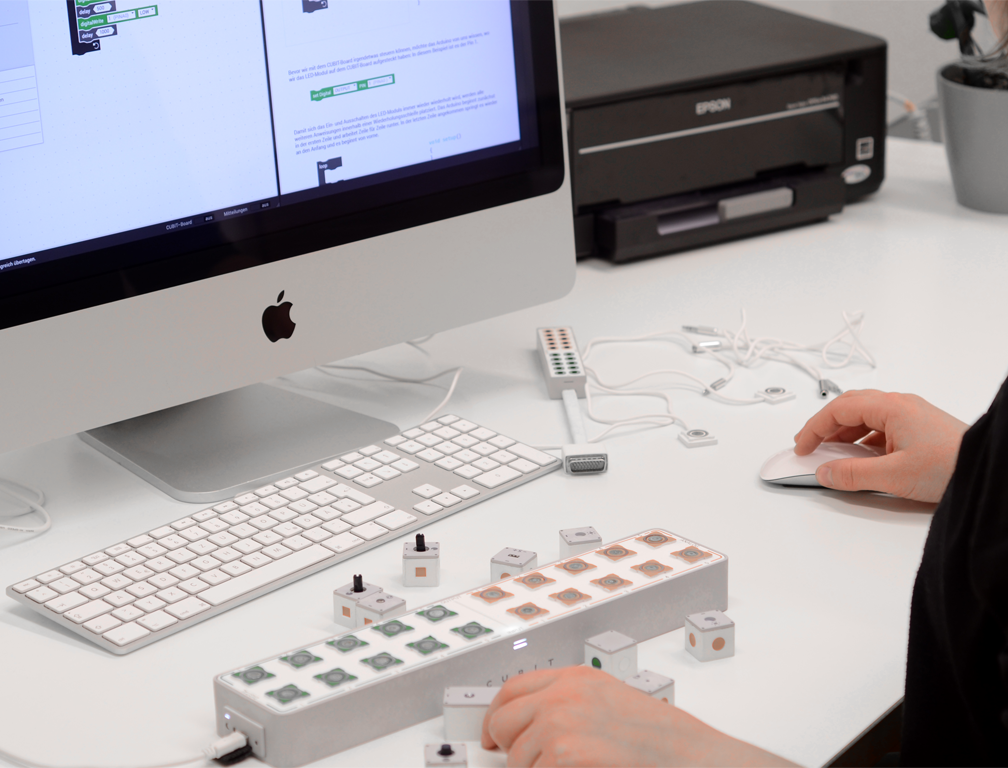
Cubit is a physical computing tool designed to help students prototype quickly and easily. It consists of two main components: hardware and software.
The hardware offers a simplified alternative to traditional prototyping tools, allowing elements to be connected seamlessly without the need for soldering or plugging in wires. The software provides an intuitive way to build code, supporting both visual and textual coding. This approach helps students understand the functionality of physical components and how to use them either independently or in combination with one another.
At the bottom of this page, you’ll find an example video showcasing a practical use case of Cubit in action.
Hardware
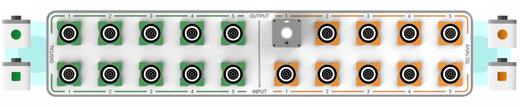
Colour and Shape Code
The breadboard serves as the interface between the computer system and the components that transmit information. In physical computing, information can be transferred in two ways: digital, which operates in binary (on or off), and analog, which provides a range of values between 0 and 1023. To differentiate these, green is used for digital signals and orange for analog signals, as shown on the breadboard below.
Additionally, a second divider separates input modules from output modules. Input modules, which gather information and send it to the computer, are represented as square elements. Output modules, responsible for transmitting information from the computer, are symbolized as circular elements.
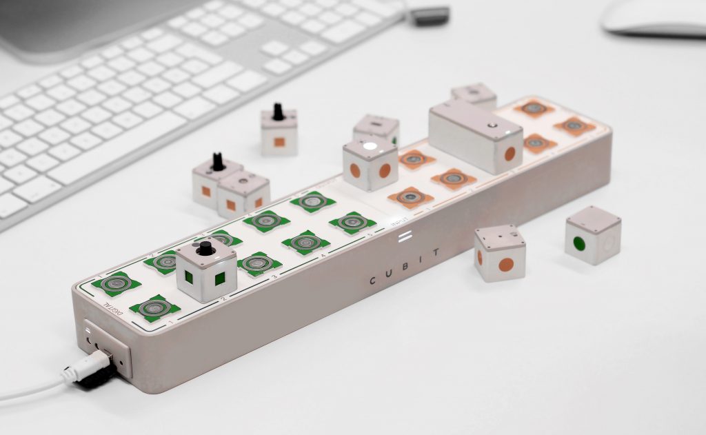
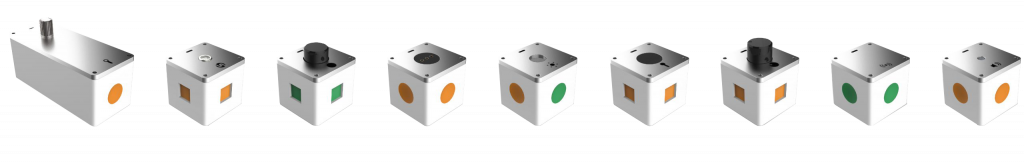
Cubes
The input and output elements are designed as cubes, making them easy to connect by simply placing them onto the breadboard. Color and shape indicators ensure proper placement, while a built-in magnet system securely connects the elements. A three-point spring contact links the interface for seamless functionality. To confirm a successful connection, an LED light on top of the cube illuminates.
Software
Coding Interface
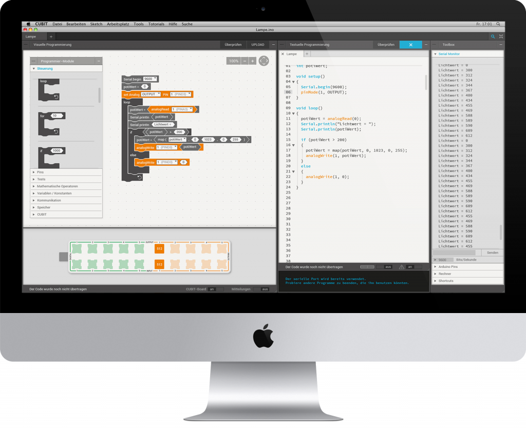
This is the main view of the Cubit software, divided into four distinct sections. On the left-hand side is the visual coding window, where functional code can be created by assembling code blocks. These blocks, available in the library on the far left, are designed with shapes that indicate compatibility with one another. Values within the blocks can be easily adjusted by overwriting them to suit specific needs.
Below the visual coding window is a representation of the breadboard. This section mirrors the cubes placed on the physical breadboard, allowing users to verify correct placement. Color coding visually connects the elements in the hardware to their corresponding parts in the visual code, ensuring an intuitive overview.
Next to the visual coding area is the automatically generated code, written in simplified C++ and utilizing a dedicated library to handle functionality. This code is ideal for advanced users who want to directly refine or expand their projects by editing the generated script.
On the right-hand side the serial monitor display is located. This section visualizes the input values received from the hardware, providing real-time feedback. Users can use this information to tweak their code and fine-tune the behavior of their project to meet specific requirements.
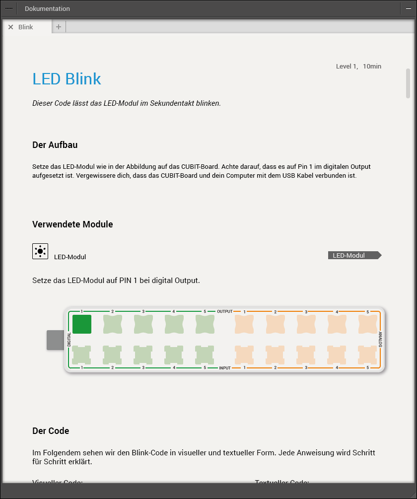
Reference Work
The reference work provides detailed explanations of each cube and its compatible connections. It serves as a comprehensive guide, outlining the functionalities and interrelationships of the different components. Step-by-step instructions illustrate various setups, offering clear examples to help users understand how to build different configurations. By following these guided examples, users can gain hands-on experience and deepen their understanding of how to create diverse prototypes, ultimately enabling them to experiment and innovate with ease.
Search Window
The search window allows users to easily search for modules and their features. By typing in a keyword or request, the software instantly provides suggestions for relevant modules and their possible combinations. This feature streamlines the process of finding the right components for a project, saving time and enhancing efficiency. To further assist with navigation, color coding is used to distinguish between analog and digital modules, making it clear at a glance which type of component you’re working with. Some cubes, like the LED module in the example, are versatile and can function as both analog and digital, showcasing their flexibility in various applications. This dynamic search and filter system empowers users to quickly identify the right modules and experiment with different configurations for their projects.
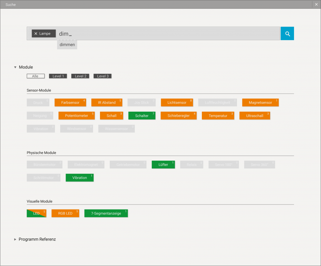
Image Video
This video provides a visual demonstration of how the product functions.